Transformer Fundamentals
Voltage Drop Calculator for Transformer Feeders
Enter the load current, one-way cable length, resistance, reactance and power factor for the circuit, then check the load-end voltage against the equipment requirement.
Use the voltage drop calculator to estimate the voltage change along an AC feeder. Enter the load current, one-way cable length, resistance, reactance and power factor for the circuit, then check the load-end voltage against the equipment requirement.
AC feeder voltage drop calculator
Estimate voltage drop, percentage and approximate load-end voltage from the circuit inputs.
Formula: ΔV = √3 × I × L / 1000 × (R × PF + X × √(1 − PF²))
Estimate only. Enter one-way cable length and conductor impedance at the intended operating temperature. Three-phase mode assumes a balanced circuit and line-to-line supply voltage.
Enter the circuit conditions
Select single-phase two-wire or balanced three-phase AC. Enter supply voltage, current, one-way length in metres, resistance and reactance in ohms per kilometre, and lagging power factor. Use conductor impedance at the intended operating temperature. The three-phase voltage is line-to-line.
Approximate feeder voltage drop
Single phase: ΔV = 2 × I × L / 1000 × (R × PF + X × √(1 − PF²))
Balanced three phase: ΔV = √3 × I × L / 1000 × (R × PF + X × √(1 − PF²))
Read the worked example
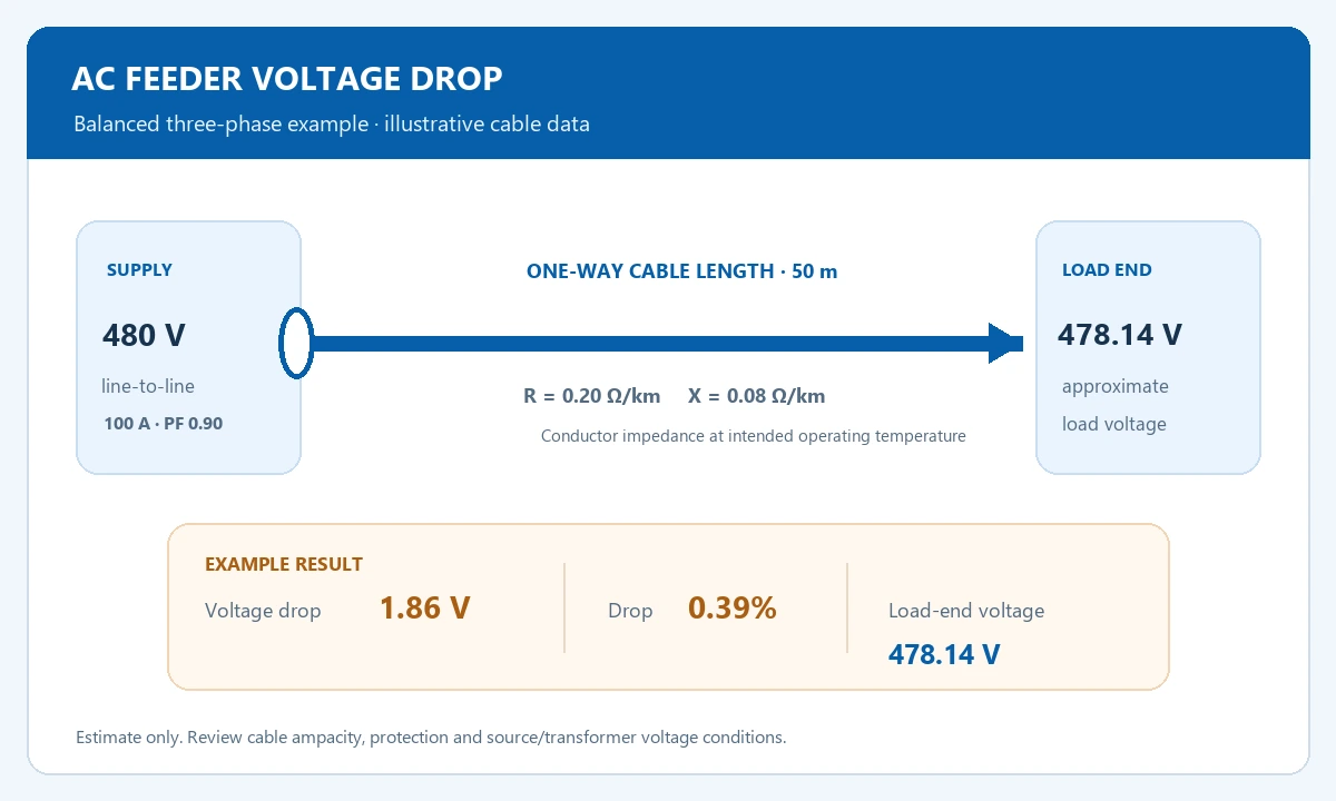
For a balanced 480 V feeder carrying 100 A over 50 m, take R = 0.20 ohm/km, X = 0.08 ohm/km and power factor = 0.90. The approximate line-to-line drop is 1.86 V, or 0.39%, leaving about 478.14 V at the load. These are illustrative input values; enter the selected cable's actual data.
| Item or condition | What to compare | Input or result |
|---|---|---|
| Supply and load | 480 V · 100 A · PF 0.90 | Balanced three-phase AC |
| Cable example | 50 m; R 0.20; X 0.08 ohm/km | One-way length |
| Calculated result | 1.86 V; 0.39% drop | 478.14 V at load |
Separate the cable from the source
This calculation estimates the feeder component of voltage change. Add source variation, transformer regulation and starting conditions in the overall system study. Review conductor ampacity, protective-device coordination and installation conditions with the electrical designer.
Keep line voltage and current quantities consistent in a balanced circuit.
Calculate Feeder CurrentConvert a transformer rating and voltage into a current input.
Review Transformer CapacityInclude source and transformer conditions in the system review.
Review Three-Phase TransformersConnect feeder voltage and load requirements to equipment selection.
Frequently asked questions
Which length should I enter?
Enter one-way cable length. The single-phase formula accounts for the outgoing and return path.
Can this calculator select cable size?
Use its result alongside ampacity, installation, thermal and fault-duty requirements in the electrical design.
Review feeder voltage and transformer capacity
Share the conductor data, circuit length, load conditions and source requirements for an electrical design review.