Transformer Fundamentals
Inductance and Transformer Magnetic Coupling
It helps explain how coils store magnetic energy and how coupled windings transfer energy in a transformer.
Inductance describes the relationship between current and magnetic flux linkage. It helps explain how coils store magnetic energy and how coupled windings transfer energy in a transformer.
Read voltage and current change together
For a linear inductor with constant inductance, voltage is L times the rate of change of current. A larger inductance requires more voltage for the same rate of current change. The henry is the SI unit of inductance.
Linear-inductor relationship
v = L × di/dt
For the same current-change rate, a larger L requires a larger voltage. This simple relationship assumes constant inductance and does not describe every magnetic component across all operating conditions.
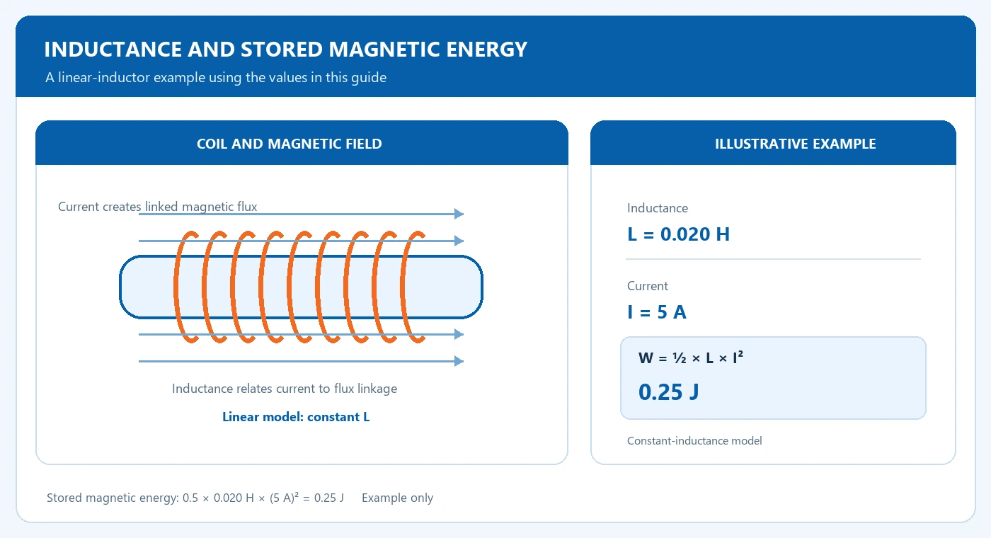
Follow a stored-energy example
Under the constant-inductance model, stored energy is one half of L times current squared. An illustrative 0.020 H coil carrying 5 A stores 0.25 J. Real magnetic components can change behavior with current, frequency and core saturation.
| Item or condition | What to compare | Input or result |
|---|---|---|
| Inductance | Henry (H) | Current and flux linkage |
| Illustrative energy | 0.5 × 0.020 H × (5 A)² | 0.25 J |
| Transformer model | Mutual and leakage terms | Use equipment data |
Example — constant-inductance model
W = ½ × L × I²
W = 0.5 × 0.020 H × (5 A)² = 0.25 J
Illustrative result only. Actual magnetic components can vary with current, frequency and core saturation.
Distinguish coupling from leakage
Mutual inductance describes flux coupling between windings. Leakage inductance relates to flux that does not link both windings completely. Transformer system studies use the manufacturer's appropriate equivalent-circuit or impedance data for the operating condition.
Mutual inductance
Describes how changing current in one winding links flux with another winding.
Leakage inductance
Represents flux that does not link all windings; use the manufacturer's model and test data.
Frequently Asked Questions
Is a transformer simply one inductor?
It has coupled windings whose magnetic and electrical relationships are described together.
Can one inductance value describe all operating conditions?
Use the model and test conditions appropriate to frequency, current and the magnetic design.
Connect magnetic coupling to your project
Use transformer operating and test data when reviewing equivalent-circuit or transient behavior.