Transformer Fundamentals
How Does a Transformer Work?
Learn how voltage ratio, current and rated capacity connect to an industrial specification.
A transformer transfers AC power between circuits through electromagnetic induction. Alternating current in the primary winding creates changing magnetic flux in the core; that flux induces voltage in the secondary winding. The turns ratio sets the ideal voltage ratio, while the connected load determines secondary current.
How magnetic induction transfers energy
The AC source drives alternating current through the primary winding. Its changing magnetic field produces alternating flux in the laminated magnetic core. The core guides this flux so it links the secondary winding, where Faraday’s law describes the induced voltage. The two windings are magnetically coupled without being electrically connected in a standard isolated transformer.
The frequency is set by the supply. Core material and geometry, winding design, insulation, cooling and load duty all affect the transformer rating and operating performance.
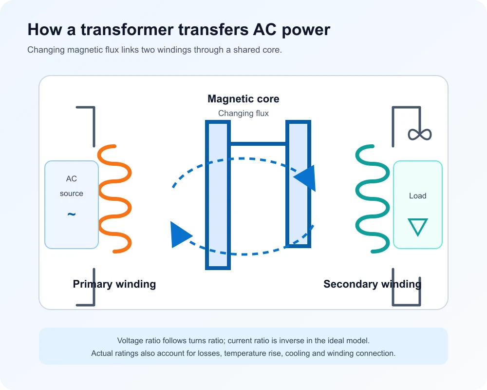
Connect turns ratio, voltage and current
For an ideal single-phase transformer, voltage follows the winding turns ratio: Vp / Vs = Np / Ns. Current changes in the inverse proportion: Ip / Is = Ns / Np. A step-down design supplies lower secondary voltage and correspondingly higher current for similar apparent power. Three-phase line values also depend on the winding connection, so use the product schedule rather than applying a single-phase ratio directly to every terminal value.
| Part or condition | Role | Specification input |
|---|---|---|
| Primary winding | Receives the AC supply | Rated input voltage |
| Magnetic core | Links winding flux | Frequency and core design |
| Secondary winding | Supplies the load | Output voltage and current |
Relate the principle to a transformer rating
A nameplate rating states the apparent power the design is intended to carry under its specified conditions. For a balanced three-phase system, line current can be estimated from I = S / (√3 × VLL). As an illustration, 1,000 kVA at 480 V line-to-line is about 1,203 A; at 13.8 kV line-to-line it is about 41.8 A. These are ideal calculation examples, not a substitute for the transformer nameplate, connection diagram or project specification.
Real units have winding resistance, leakage flux and core losses. Temperature rise and cooling limits also matter. For project sizing, share the load schedule, primary and secondary voltages, frequency, phase, installation environment and required standard with the engineering team. Use the transformer selection guide to organize those inputs.
To convert nameplate kVA and winding current, use the kVA to amps calculator with the voltage for that same transformer side.
To identify winding and core marks on project drawings, read the transformer symbols guide and confirm each connection against the approved schedule.
Frequently Asked Questions
Why does a transformer need alternating current?
Alternating current creates a changing magnetic flux in the core. That changing flux induces voltage in the secondary winding; steady direct current does not sustain this transformer action after the switching transient.
Does a transformer increase power?
No. A transformer changes voltage and current levels. In an ideal transformer, input and output apparent power are equal; a real transformer delivers slightly less because of electrical and magnetic losses.
What does the turns ratio tell me?
For an ideal transformer, the primary-to-secondary voltage ratio equals the primary-to-secondary turns ratio. The current ratio is inverse, subject to winding connection and losses in a real design.
Apply transformer fundamentals to your project
Compare the required duty and product family, then confirm ratings against the project specification and approved technical documents.