Power System Fundamentals
Capacitive Reactance and Frequency
It decreases as frequency or capacitance increases, making frequency an essential input when reviewing power-system compensation.
Capacitive reactance describes a capacitor's opposition to sinusoidal alternating current. It decreases as frequency or capacitance increases, making frequency an essential input when reviewing power-system compensation.
Use consistent units
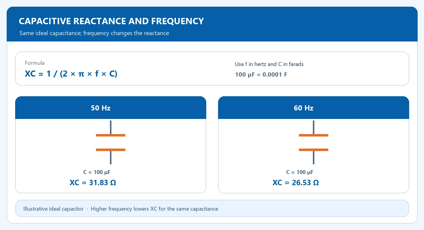
The magnitude of capacitive reactance is XC = 1 / (2 × π × f × C). Enter frequency in hertz and capacitance in farads to obtain ohms. Convert microfarads by dividing by one million before using the formula.
Capacitive reactance
XC = 1 / (2 × π × f × C)
Use f in hertz and C in farads. For example, 100 μF = 100 ÷ 1,000,000 F = 0.0001 F. The result is reactance in ohms for an ideal capacitor under sinusoidal conditions.
Compare two frequencies
For an illustrative 100 microfarad capacitor, XC is approximately 31.83 ohms at 50 Hz and 26.53 ohms at 60 Hz. At the same voltage, the higher-frequency example carries more current. Rated voltage, tolerance and the manufacturer's thermal limits remain part of component selection.
| Item or condition | What to compare | Input or result |
|---|---|---|
| Formula | XC = 1 / (2 × π × f × C) | C in farads |
| 100 microfarads at 50 Hz | 31.83 ohms | Illustrative ideal capacitor |
| 100 microfarads at 60 Hz | 26.53 ohms | Same capacitance |
50 Hz
100 μF → 31.83 Ω
60 Hz
100 μF → 26.53 Ω
Illustrative ideal-capacitor values. Confirm actual capacitor ratings, voltage, tolerance and thermal limits with the manufacturer.
Connect the result to a system study
Power-factor correction adds capacitive behavior to a network containing inductive loads and transformers. Review switching, harmonics and possible resonance with the system designer before specifying a bank. Use the actual component and network data in the study. For frequency-related conductor losses, see skin effect and AC conductor losses.
Include system context
A reactance comparison alone does not select a compensation bank. Include operating voltage, load profile, switching arrangement, harmonic sources and the network model in the engineering review.
Frequently Asked Questions
Why does reactance fall with frequency?
The relationship is inverse: increasing frequency reduces XC for the same ideal capacitance.
How does this relate to a transformer enquiry?
Include planned compensation equipment and harmonic-producing loads so their system interaction can be reviewed.
Review compensation with system data
Share operating voltage, load profile, proposed capacitor data and known harmonic sources for a project review.