Transformer Fundamentals
Power Factor Correction and Transformer Loading
Begin with measured demand, reactive power and waveform information before selecting a solution.
Power factor correction can change the apparent power drawn by a load. Begin with measured demand, reactive power and waveform information before selecting a solution.
Establish the operating profile
Measure kW, kVA, true power factor and harmonic current over representative load cycles. Separate displacement caused by inductive loads from waveform distortion. Record existing capacitors and switching states before selecting a correction method.
Estimate an illustrative reactive requirement
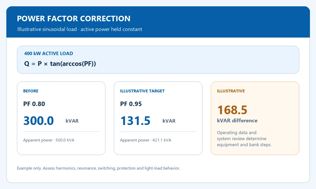
For a sinusoidal 400 kW load, estimate reactive power with Q = P × tan(arccos(PF)). At PF 0.80, Q is 300.0 kVAR. At a target PF of 0.95, Q is about 131.5 kVAR, an illustrative difference of 168.5 kVAR. The operating profile and electrical-system review determine actual bank steps and controls.
| Item or condition | What to compare | Input or result |
|---|---|---|
| Active load | 400 kW | Held constant in this example |
| Before correction | PF 0.80 · 300.0 kVAR | Q = P × tan(arccos(PF)) |
| Illustrative target | PF 0.95 · 131.5 kVAR | Estimated difference: 168.5 kVAR |
Illustrative sinusoidal calculation
Q = P × tan(arccos(PF))
400 × tan(arccos(0.80)) = 300.0 kVAR; 400 × tan(arccos(0.95)) ≈ 131.5 kVAR. The 168.5 kVAR difference is not a final equipment rating.
Coordinate and verify the design
Review harmonics, resonance, switching, protection and light-load behavior before equipment selection. After an approved change, compare kW, kVA, current and power factor at the same measurement point and under comparable conditions. Keep settings and event records.
Frequently Asked Questions
Does correction reduce the active load itself?
Correction addresses the relationship between active and apparent power. Assess active energy use and equipment losses separately.
Can I choose a capacitor bank from one spot reading?
Use a representative operating profile and electrical-system review to select equipment and controls, including harmonic and switching requirements.
Review power factor correction for your application
Share representative operating data, harmonic measurements, capacitor switching states and system conditions for an engineering review.