Transformer Fundamentals
Reactive Power and the Power Triangle
Read kVAR alongside active power in kW, apparent power in kVA and power factor when reviewing a transformer-fed load.
Reactive power describes the exchange of energy associated with electric and magnetic fields in an AC system. It is part of the relationship between real work, apparent power and the operating conditions of the connected load.
Read P, Q and S together
For a balanced sinusoidal example, apparent power S, active power P and reactive power Q satisfy S squared = P squared + Q squared. Inductive and capacitive conditions use opposite reactive-power signs under the chosen convention. Record that convention with the measurement.
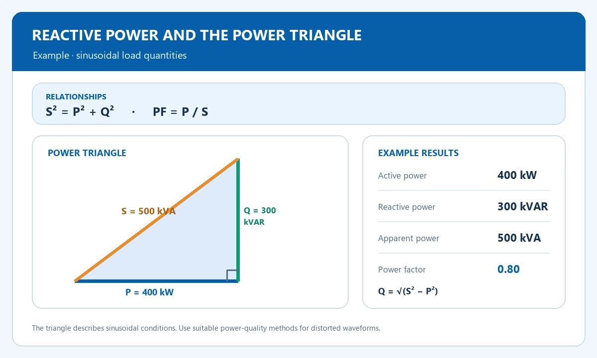
Power triangle relationships
S² = P² + Q² · PF = P / S
For this sinusoidal example, Q = √(500² − 400²) = 300 kVAR and PF = 400 / 500 = 0.80. Use kW, kVAR and kVA consistently with the instrument’s sign convention.
Use the power triangle
An illustrative load with P = 400 kW and S = 500 kVA has Q = 300 kVAR and power factor = 0.80. Reducing the magnitude of Q while maintaining P reduces S in this example. The triangle describes sinusoidal conditions; distorted waveforms require the appropriate power-quality measurement method.
| Item or condition | What to compare | Input or result |
|---|---|---|
| Active power P | 400 kW | Work and useful energy transfer |
| Reactive power Q | 300 kVAR | Sinusoidal example |
| Apparent power S | 500 kVA | PF = 400 / 500 = 0.80 |
These relationships are useful for sinusoidal conditions. When harmonics distort the waveform, use measurements and calculations appropriate to the power-quality instrument and system.
Prepare an operating profile
Collect simultaneous kW, kVA, power factor and kVAR readings over representative operating conditions. Identify large motors, drives and switched capacitor banks. Use the measurements to review capacity and any proposed compensation with the electrical designer.
Frequently Asked Questions
Where does kVAR fit?
kVAR is the unit for reactive power. One kVAR equals 1,000 volt-amperes reactive.
Should compensation be fixed at one value?
Select the arrangement from the operating profile, switching requirements and harmonic assessment.
Review reactive power in your application
Share representative kW, kVA, power-factor and kVAR readings together with the load profile, voltage, phase and harmonic conditions.