Electrical Conductor Fundamentals
Skin Effect and AC Conductor Losses
It helps explain why AC resistance can differ from a conductor's DC resistance.
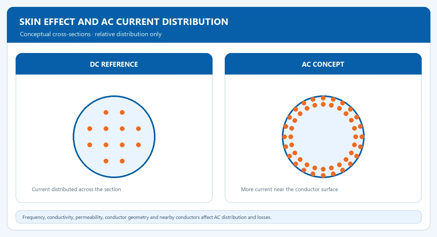
Skin effect causes AC current density to become uneven across a conductor, with more current concentrated near the surface as frequency increases. It helps explain why AC resistance can differ from a conductor's DC resistance.
Compare current distribution
A DC resistance calculation uses conductor material, length and area. Under AC conditions, magnetic fields within the conductor change the current distribution. Frequency, conductivity, permeability and conductor geometry influence the resulting skin depth.
| Item or condition | What to compare | Input or result |
|---|---|---|
| DC reference | Material, length and area | DC resistance |
| AC operation | Frequency and geometry | Uneven current distribution |
| Project review | Harmonics, current and cooling | AC loss and thermal data |
Connect frequency to heating
For the same material, skin depth decreases as frequency rises. Conductors carrying harmonic currents therefore require evaluation beyond the fundamental frequency alone. Proximity effects from nearby conductors also contribute to the current pattern and AC losses. For separate voltage and current distortion measures, review total harmonic distortion in transformer loads. For the relationship between current, resistance and heat, see Joule heating and transformer winding losses.
Frequency
Higher frequency reduces skin depth for the same material.
Conductor geometry
Size, shape and nearby conductors affect current distribution and proximity losses.
Harmonic content
Evaluate the spectrum as well as the fundamental-frequency current.
Review the offered conductor design
Request the relevant winding or bus conductor loss information for the operating duty. Include frequency, harmonic content, continuous current and cooling conditions in the technical schedule. The manufacturer determines conductor geometry and construction for the specified equipment. For the external terminal connection and interface drawings, review busbars and transformer terminal interfaces.
Technical schedule inputs
- • Operating frequency and harmonic spectrum
- • Continuous current and load profile
- • Winding or bus conductor loss data
- • Cooling and ambient conditions
Frequently Asked Questions
Does skin effect only occur at radio frequencies?
It occurs with AC; its engineering significance depends on frequency, conductor size and material.
Which load information helps the review?
Supply the load spectrum or representative harmonic measurements with current and operating frequency.
Share conductor operating data
Provide current, frequency, harmonic content and cooling conditions for a winding or bus-conductor review.
Related: AC current distribution and winding loss review.