Transformer Engineering Blog
Impedance Formula: R, X and Transformer Fault-Study Inputs
Calculate complex impedance clearly, then prepare the transformer data a fault study needs.
The basic impedance formula is Z = V/I, using voltage and current phasors for sinusoidal AC analysis. Writing Z = R + jX separates resistance from reactance. That separation lets you calculate current magnitude and the phase difference between voltage and current.
Start with the circuit connection and frequency. A resistor, an inductor and a capacitor have different impedance expressions, and series and parallel circuits combine them differently. The examples below show each decision before connecting the result to transformer test data.
Read the formula and its units
| Element or quantity | Formula | Input units |
|---|---|---|
| Complex impedance | Z = R + jX | R and X in ohms |
| Magnitude | abs(Z) = √(R² + X²) | Result in ohms |
| Resistor | ZR = R | Resistance in ohms |
| Ideal inductor | ZL = j2πfL | Frequency in Hz; inductance in H |
| Ideal capacitor | ZC = −j/(2πfC) | Frequency in Hz; capacitance in F |
| Angular frequency | ω = 2πf | Radians per second |
The symbol j represents the imaginary unit. Positive reactance is inductive; negative reactance is capacitive in this convention. For R greater than zero, the impedance angle is arctan(X/R). Software using atan2(X,R) handles quadrant information directly.
For example, Z = 3 + j4 ohms has magnitude 5 ohms and angle 53.13 degrees. With 100 V RMS at a reference angle of zero, current is 20 A RMS at −53.13 degrees: current lags voltage.
The manufacturer-authored ROHM impedance guide covers complex representation, component formulas and combination rules.
Work a series R-L-C example
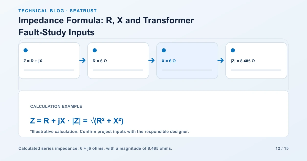
Consider an illustrative series circuit at 60 Hz with R = 6 ohms, XL = 8 ohms and XC = 2 ohms. The reactance values are specified at that frequency.
Subtract capacitive reactance from inductive reactance: X = 8 − 2 = 6 ohms.
Write the complex impedance: Z = 6 + j6 ohms.
Calculate magnitude: abs(Z) = √(6² + 6²) = 8.485 ohms.
Calculate phase angle: θ = arctan(6/6) = 45 degrees.
With 120 V RMS applied, calculate current magnitude: I = 120/8.485 = 14.142 A RMS.
Current lags the source voltage by 45 degrees because net reactance is inductive.
Check the power independently. Apparent power is 120 × 14.142 = 1,697 VA. Real power in the resistor is I²R = 14.142² × 6 = 1,200 W. The power factor is 1,200/1,697 = approximately 0.707.
| Voltage in the series example | RMS value |
|---|---|
| Resistor: IR | 84.85 V |
| Inductor: IXL | 113.14 V |
| Capacitor: IXC | 28.28 V |
| Net reactive voltage | 84.85 V |
| Source: √(VR² + (VL − VC)²) | 120 V |
Add these voltages as phasors. Simply adding their positive magnitudes would give the wrong supply voltage.
See how frequency changes reactance
Use a separate illustrative pair of ideal components: L = 20 mH and C = 100 µF. Convert those units to 0.020 H and 0.000100 F before substitution.
| Component | At 50 Hz | At 60 Hz |
|---|---|---|
| Inductor, XL = 2πfL | 6.28 ohms | 7.54 ohms |
| Capacitor, XC = 1/(2πfC) | 31.83 ohms | 26.53 ohms |
Inductive reactance increases with frequency; capacitive reactance decreases. Keep component tolerances and parasitic effects with real device data. The ideal formulas explain the direction and scale of the change at the specified frequency.
Combine parallel impedances
For parallel branches, add admittances:
1/Ztotal = 1/Z1 + 1/Z2
For a 10-ohm resistor in parallel with an ideal inductive impedance of j10 ohms, total admittance is 0.1 − j0.1 siemens. Inverting it gives Ztotal = 5 + j5 ohms, whose magnitude is 7.071 ohms.
At 100 V RMS, each branch carries 10 A RMS, but the branch currents differ by 90 degrees. Total current magnitude is 14.142 A RMS. Recording the complex values preserves this phase information throughout the calculation.
Connect the formulas to transformer data
A transformer nameplate percentage impedance uses the transformer's rated base. It is different from the ohm value of a single component in the examples above.
For a three-phase transformer, Zbase = VLL²/S, with voltage in volts and apparent power in VA. On a 1,000 kVA, 480 V line-to-line base, Zbase = 0.2304 ohm. A 5% impedance corresponds to a magnitude of 0.01152 ohm on that secondary base.
Keep percentage impedance, reference temperature, tap position, load-loss data and the test report together. They allow the study engineer to build the appropriate equivalent circuit and combine it with the source and downstream network. Follow the transformer impedance guide for the terminal fault-current example and project input register.
Check the calculation before handing it over
| Check | What to confirm |
|---|---|
| Units | mH converted to H; µF converted to F; kVA converted to VA |
| Frequency | Reactance values match the stated frequency |
| Connection | Series impedances added directly; parallel branches combined through admittance |
| Sign | Capacitive reactance negative and inductive reactance positive |
| Voltage convention | RMS, line-to-line and phase values clearly identified |
| Transformer base | Rating and winding voltage match the impedance base |
For resistive examples and unit checks, use the Ohm's law guide.
FAQ
Why can a voltmeter reading alone not give complex impedance?
You also need current magnitude and the voltage-current phase relationship. The ratio of RMS magnitudes gives impedance magnitude, while phase identifies its resistive and reactive components.
Can the same capacitor have different reactance values?
Yes. Capacitive reactance varies inversely with frequency and capacitance. State the frequency beside the result.
What belongs beside a transformer impedance value?
Record transformer ID, kVA base, winding voltage, tap, reference conditions and the manufacturer's test information.
Provide the transformer study inputs
Send the transformer rating, winding voltages, percentage impedance and system-study requirements with the enquiry.