Transformer Technical Guide
Electrical Impedance in Transformer Selection
Read percentage impedance, work through a fault-current example, and collect the right study inputs.
Electrical impedance describes how an AC circuit opposes current. It combines resistance and reactance, so both magnitude and phase matter. In a transformer specification, percentage impedance is a particularly useful value for reviewing voltage performance, fault-current studies and the coordination of connected equipment.
Distinguish resistance from reactance
Resistance represents the component associated with real power loss. Reactance represents the effect of energy storage in magnetic or electric fields. For sinusoidal steady-state analysis, impedance is written as Z = R + jX, where R and X are measured in ohms. For R = 3 ohms and X = 4 ohms, the magnitude is 5 ohms. A 100 V RMS supply across that impedance produces 20 A RMS. The phase relationship still matters when calculating power.
Read the transformer's percentage impedance
Use the value supplied for the actual transformer, together with its kVA base, winding voltages, tap and test conditions. Percentage impedance is related to the proportion of rated voltage required to circulate rated current in the specified short-circuit test. Keep a nameplate photograph and the manufacturer's test report together. Values from different equipment must be placed on consistent bases before they are combined in a study.
Work through a three-phase example
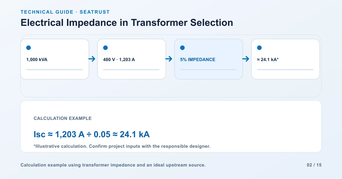
Consider an illustrative 1,000 kVA, 480 V line-to-line transformer with 5% impedance. Its rated secondary current is 1,000,000 divided by (1.732 times 480), approximately 1,203 A. With an infinite upstream source, nominal voltage, a three-phase bolted fault at the secondary terminals, and no motor contribution or impedance-tolerance adjustment, the estimate is 1,203 divided by 0.05, approximately 24.1 kA symmetrical RMS.
| Input or result | Value | Meaning |
|---|---|---|
| Transformer rating | 1,000 kVA | Three-phase nameplate base for this example |
| Secondary voltage | 480 V | Line-to-line RMS |
| Impedance | 5% = 0.05 per unit | On the transformer rating base |
| Rated current | Approximately 1,203 A | 1,000,000 / (1.732 x 480) |
| Terminal fault current | Approximately 24.1 kA | 1,203 / 0.05 under the stated assumptions |
Prepare the network study and impedance data sheet
For an installation study, provide the utility source information, transformer test data, cable lengths and characteristics, and connected sources or motors. Include operating arrangements and the specified tolerances. These inputs affect the current available at each fault location. The engineer uses the resulting study to check protective-device duties and equipment ratings at the relevant locations.
Attach the impedance value to a specific transformer and winding base. A useful record identifies the rated kVA, winding voltage, tap position, reference temperature and the source of the value. If a test report gives load loss as well as impedance, retain both for the engineer who determines the resistive and reactive components.
| Data field | Example record | Why it matters |
|---|---|---|
| Equipment ID | T1 | Connects the value to the correct drawing |
| Rating base | 1,000 kVA | Defines the per-unit base |
| Voltage base | 480 V line-to-line | Identifies the winding used in the calculation |
| Impedance | 5% on the stated base | Enters the fault-current model |
| Source impedance | Utility study input | Adds the upstream network contribution |
| Downstream circuit | Cable size, material and route length | Establishes impedance to the fault location |
For the example above, the three-phase base impedance is Zbase = VLL² / S = 480² / 1,000,000 = 0.2304 ohm. A 5% value therefore corresponds to 0.01152 ohm on this secondary base. Keep the complex impedance components and X/R information with the full study.
For step-by-step R, L and C calculations, use the impedance formula examples.
Compare replacement and parallel-operation data
When replacing a transformer, compare its impedance and rating information with the existing study and connected equipment. If transformers will operate in parallel, send the complete data for each unit, including ratio, tap, phase sequence and phase displacement. Ask the project engineer to review load sharing and protection coordination before procurement is finalized.
FAQ
Can I use the example current as a project equipment rating?
Use the completed project short-circuit study, with the actual source, transformer and circuit data, for equipment selection.
Which impedance details belong in an enquiry?
Include the required percentage impedance, rating base, applicable specification and the intended operating arrangement.
Provide the required impedance
Send capacity, winding voltages, impedance and system-study requirements with your transformer enquiry.