Transformer Engineering Blog
High Voltage Direct Current: Where AC Transformers Meet the Converter Station
Map the AC equipment, converter station and DC link before defining the transformer interface.
High voltage direct current, usually shortened to HVDC, transmits power as direct current between converter stations. The networks connected to the stations are often AC. Converters change power between AC and DC; transformers on the AC side provide the voltage and electrical interface specified for the converter station.
That distinction matters when preparing a project brief. A transmission transformer changes AC voltage. A converter changes the form of electrical power. Each has its own ratings, controls, insulation duties and interfaces.
Review the station interface checklist
Identify each stage of the connection
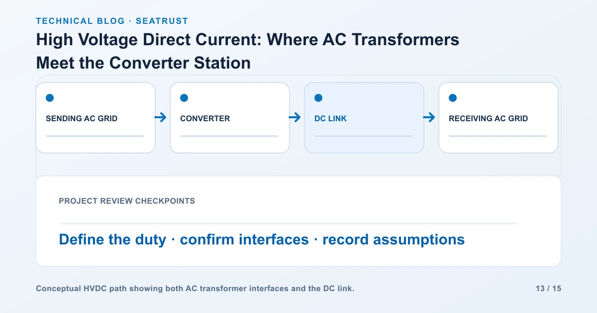
For a point-to-point link connecting two AC systems, trace the following sequence:
Sending AC system → converter transformer → sending converter → DC line or cable → receiving converter → transformer → receiving AC system
| Stage | Main job | Information shown on the project diagram |
|---|---|---|
| AC connection | Connect the station to the network | AC voltage, frequency and connection point |
| Converter transformer | Match the AC network and converter-side requirements | Winding ratings, connections and terminal interfaces |
| Converter | Convert between AC and DC under the control scheme | Converter technology and operating direction |
| DC link | Carry power between stations | Link arrangement, voltage, current and route |
| Receiving AC connection | Deliver power into the receiving network | AC connection requirements and operating conditions |
The project may use overhead lines, cables or a different terminal arrangement. A back-to-back station can interconnect AC systems through converters at one location, without a long DC transmission line.
Understand why a project considers HVDC
HVDC is considered for long-distance power transfer, cable connections, remote generation and grid interconnection. Hitachi Energy's HVDC overview groups applications including offshore wind, remote generation, interconnecting grids and back-to-back connections.
The choice is a system decision. Compare the whole route and its terminal stations, rather than applying a single distance threshold to every project.
| Project question | Information needed for comparison |
|---|---|
| How much power moves, and in which direction? | Rated transfer, operating range and future expansion |
| Which networks are connected? | Frequency, system strength and operating constraints |
| What route is available? | Overhead, underground or submarine route and physical constraints |
| What terminal infrastructure is required? | Converter stations, AC switchyards, transformers and auxiliary systems |
| What operating behavior is required? | Power control, outages, restoration and availability requirements |
Separate line-commutated and voltage-source systems
Line-commutated converters, or LCC, and voltage-source converters, or VSC, are established HVDC technology families. They have different switching arrangements and interactions with the connected AC system. Hitachi Energy lists both families within its HVDC offering.
The converter-system designer selects the topology and defines the transformer interface. Record that selection early. Changing the converter arrangement can change winding duties, insulation requirements, harmonic conditions, control interfaces and the station layout.
| Design item | Information to request |
|---|---|
| Converter family | Approved LCC or VSC system arrangement |
| Transformer grouping | Number of units, winding arrangement and redundancy plan |
| AC system | Operating voltage, frequency and fault-study inputs |
| Converter-side duty | Required voltage, waveform, harmonic and insulation information |
| Cooling and environment | Ambient range, heat rejection and site constraints |
Prepare the station interface checklist
Treat the converter transformer as equipment within a coordinated station. Its specification needs more than the link's headline MW or DC voltage.
| Interface | Data owner | Deliverable for review |
|---|---|---|
| AC network conditions | Network operator and system designer | Voltage range, frequency and system-study requirements |
| Converter-side winding duty | Converter-system designer | Winding and terminal requirements |
| Insulation coordination | Station engineering team | Approved insulation and overvoltage requirements |
| Terminations | Transformer and connection suppliers | Mating details, orientation and phase identification |
| Protection and control | Protection/control team | Signals, alarms, trips and interface responsibilities |
| Civil and access | Civil/site team | Loads, foundation, delivery route and replacement access |
| Testing | Purchaser and system designer | Test specification and acceptance requirements |
Use consistent equipment IDs across these documents. If a terminal changes, update the transformer drawing, connecting equipment and site arrangement together.
Work through a specification handover
Consider a project brief that initially says only “HVDC link connecting two AC systems.” The first useful improvement is a block diagram naming the two AC connection points, converter stations and DC link. The next is a responsibility table identifying who defines each transformer-side condition.
The transformer request then adds:
The approved station single-line diagram and converter arrangement.
The electrical ratings and operating cases supplied by the station designer.
Converter-side waveform, insulation and terminal requirements.
Site conditions, cooling duty and installation constraints.
Required studies, tests and documentation.
The supply boundary for connections, auxiliaries and commissioning activities.
This sequence gives reviewers a connected data package instead of unrelated headline ratings. For conventional AC receiving-station connections, use the transmission-line interface guide.
FAQ
Does a transformer convert AC into DC?
A conventional power transformer changes AC voltage through magnetic coupling. Converter equipment performs AC/DC conversion in an HVDC station.
Where is a converter transformer located?
It connects the AC system with the converter-side equipment in the station arrangement. The approved design defines the exact windings and terminal interfaces.
Is DC-link voltage enough to choose the transformer?
The specification also needs converter-side winding duties, AC conditions, insulation, harmonic information, cooling and project tests.
Does every HVDC project need a long DC line?
Back-to-back stations can connect AC systems at one site. Other projects use overhead or cable links between separated stations.
Prepare the high-voltage project brief
Start with the required equipment duty, then identify suppliers whose documented product range covers it. Converter-transformer procurement requires that specific duty to be confirmed.
For the conventional AC transformer scope of your project, send the single-line diagram, winding voltages, capacity, frequency, operating duty and site information to Seatrust. The substation equipment guide explains how switching, protection and transformer responsibilities fit together.