Transformer Technical Guide
Transmission Lines and the Transformers at Their Terminals
Trace the receiving-station interface from network conditions to transformer terminals.
A transmission line carries electrical power between parts of a power network. Transformers at network connection points can change the voltage for transmission or downstream distribution. A project specification needs both the transformer's ratings and the conditions of the network to which it connects.
Locate the transformer in the network
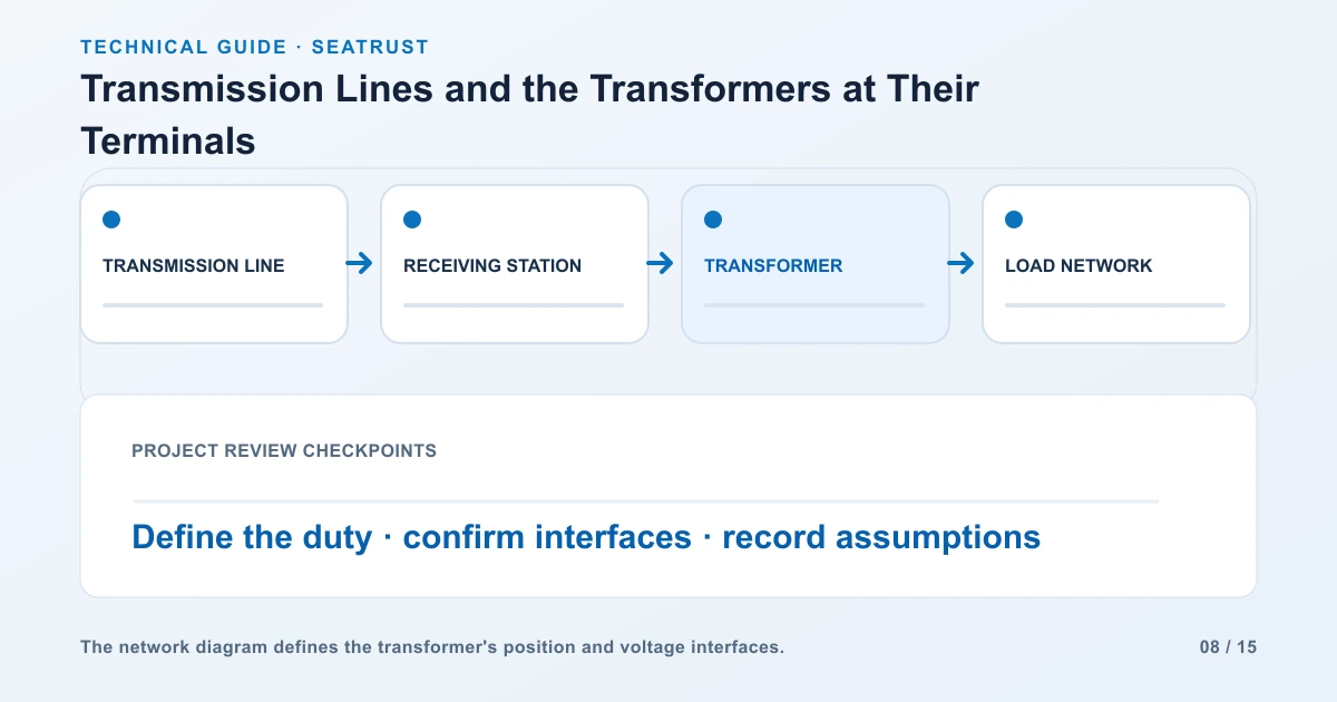
Read the project single-line diagram from the source through the line to the receiving station and connected loads. Mark each voltage level and the point of voltage transformation. Distinguish the line's nominal voltage from the individual equipment ratings listed in the project specification.
Collect network operating conditions
Obtain the operating voltage range, frequency and system fault information from the responsible network designer or operator. Include intended loading, future expansion and contingency requirements. These inputs support the transformer and connected equipment review.
| Project field | Record |
|---|---|
| Network location | Sending or receiving station and circuit identifier |
| Electrical conditions | Nominal voltage, operating range, frequency and fault data |
| Connection | Bus or cable details and terminal arrangement |
| Protection | Project insulation and protective requirements |
| Scope boundary | Supply and installation responsibilities |
Coordinate insulation and protection
Line interfaces expose equipment to the operating and transient conditions of the network. The project team coordinates insulation requirements, surge protection, grounding and protective devices. Supply the approved requirements and connection arrangement to the transformer manufacturer.
Define the delivery boundary
Clarify who supplies line terminations, buswork, cables, protection equipment and civil work. Record the transformer's terminal details and the drawings needed by the site team. A clear boundary avoids an unassigned connector or missing installation component.
架空与电缆接入比较
| Interface | Line-side information | Transformer-side coordination |
|---|---|---|
| Overhead line | Conductor arrangement, station entry and mechanical support | Bus connection, bushing position and insulation coordination |
| Underground or submarine cable | Cable system rating, termination design and route | Cable-box or bus interface, support and installation space |
| Existing receiving station | Existing drawings, fault study and operating limits | Replacement compatibility and revised study inputs |
| New receiving station | Supply agreement, load forecast and approved layout | Transformer rating, terminals and delivery plan |
The supply boundary may include several parties. State who supplies the line termination, flexible connection, surge protection, buswork and testing. Use the connection drawing to identify each boundary physically.
电压与电流比较
For an illustrative balanced three-phase transfer of 30 MW at a power factor of 0.95, line current is I = P / (√3 × VLL × PF). At 33 kV the result is approximately 552 A; at 132 kV it is approximately 138 A.
The higher voltage reduces current by a factor of four in this comparison. With the same conductor resistance, I²R loss would be one-sixteenth. A real line comparison also includes conductor design, charging, insulation, route, terminal equipment and system studies.
Read the HVDC connection guide for the separate conversion stages used when the transmission link carries direct current.
FAQ
Why are high voltages used for transmission?
For the same transmitted power and power factor, increasing voltage reduces current. Line design then balances losses, insulation, cost and system requirements.
Can I specify the transformer from line voltage alone?
Provide capacity, both winding voltages, duty, fault conditions and the project requirements as well.
Specify the receiving transformer
Share the line interface and downstream requirements for a project-specific equipment review.