Transformer Technical Guide
What Is a Substation and How Does Its Equipment Work Together
Follow the power path, assign equipment duties, and prepare a coordinated transformer brief.
A substation is a connection point in an electrical power system where equipment can switch, protect, measure and, where required, transform electrical power. Its design depends on the network duty, voltage levels and loads. The transformer is one part of that coordinated system.
Start with the station's job
A substation brings power circuits together and provides switching, protection and measurement. Many substations also change voltage through transformers. A generating station connection, a transmission receiving station and an industrial distribution station have different duties. Begin a project brief with the incoming network, outgoing loads and operating purpose so each item of equipment has a defined role.
| Project | Operating question | Transformer information |
|---|---|---|
| Generation connection | Where does generated power enter the network? | Generator-side voltage, grid-side voltage and export duty |
| Transmission connection | Which incoming and outgoing circuits must remain available? | Network voltage levels, capacity and operating arrangements |
| Industrial distribution | Which loads must run during planned maintenance? | Load schedule, utilization voltage, future demand and installation environment |
Read a simple power path
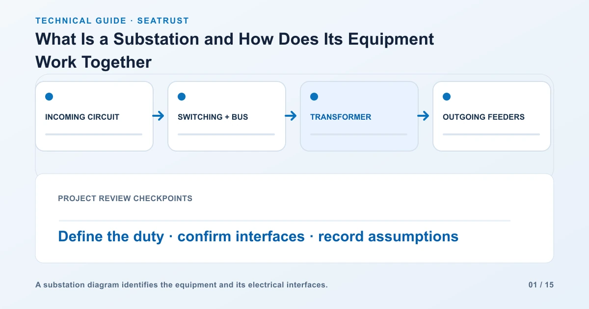
An illustrative arrangement is incoming circuit, switching and bus equipment, transformer, secondary switching equipment and outgoing feeders. Read that sequence on the single-line diagram, then identify the actual voltage and rating labels. The diagram records electrical connections; use the site layout separately for physical positions and access. Give both documents matching equipment identifiers so reviewers can trace the same transformer.
Distinguish the equipment functions
The transformer changes voltage. Circuit breakers interrupt current within their assigned duties, and protection systems determine when a fault should trigger disconnection. Instrument transformers provide signals for metering or protection. Buses connect circuits within the station. Ask the project designer to identify the operating and maintenance arrangement before equipment specifications are finalized.
| Function | Typical equipment | Question for the project brief |
|---|---|---|
| Voltage conversion | Power or distribution transformer | What are the required winding voltages and capacity? |
| Circuit connection | Buses and switching devices | Which circuits operate together? |
| Fault protection | Protection system and circuit breakers | What fault duties and operating scheme apply? |
| Measurement | Instrument transformers and meters | Which signals and accuracy requirements are needed? |
| Safe maintenance access | Isolation arrangements and site layout | How will equipment be isolated and accessed? |
Define normal operation and planned outages
Explain which loads must remain supplied when a transformer or incoming circuit is unavailable. Supply the expected load profile, expansion plan and any permitted load-shedding arrangements. These operating requirements help the designer evaluate the number of circuits and transformers. Keep approved normal and outage arrangements with the enquiry instead of relying on a capacity figure alone.
Consider a facility with two transformers supplying separate bus sections. During normal operation, each transformer supplies its own section and the bus tie is open. If one transformer is removed for maintenance, the project team needs to decide which loads may transfer, which loads must stop, and whether the remaining transformer and connecting equipment can carry the transferred load.
Record the approved operating sequence on the single-line diagram. Include any interlocking, transfer conditions and load-shedding requirements. A second transformer creates an alternative supply path only when the connections, ratings and operating arrangements support that path.
| Operating state | Information to show | Review output |
|---|---|---|
| Normal service | Source availability, bus tie position, load on each section | Approved normal diagram |
| One transformer unavailable | Critical load, transferable load, remaining capacity | Permitted outage arrangement |
| Return to normal | Re-energization sequence and authorized operator | Approved restoration procedure |
Use the switchyard interface guide to coordinate physical terminals after the electrical arrangement is agreed.
Prepare the transformer enquiry
Provide required kVA or MVA, winding voltages, frequency, phase arrangement, connection, installation environment and cooling duty. Include the network fault information and the insulation and protection requirements prepared by the project team. Attach the terminal arrangement and delivery route. State who supplies bus connections, cables, protection interfaces and civil work so each interface has an owner.
FAQ
Does every substation contain a power transformer?
The equipment follows the station's function. Some stations mainly switch circuits; others include voltage transformation.
What should be supplied before selecting a transformer?
Start with the diagram, voltage levels, capacity, frequency, duty and installation requirements.
Define the transformer in your station project
Share the diagram and required ratings to begin a transformer specification review.