Instrument Transformer Fundamentals
Current Transformers for Metering and Protection
Match the ratio and accuracy duty to the instrument and the current expected in the monitored circuit.
A current transformer, or CT, produces a secondary current related to the primary current for metering or protection. Match the ratio and accuracy duty to the instrument and the current expected in the monitored circuit.
Connect ratio to instrument settings
A 400:5 CT has an 80:1 ratio. In an ideal example, 200 A primary current corresponds to 2.5 A secondary current. Configure the meter or relay for the actual ratio and confirm terminal polarity and phase identification against the drawing.
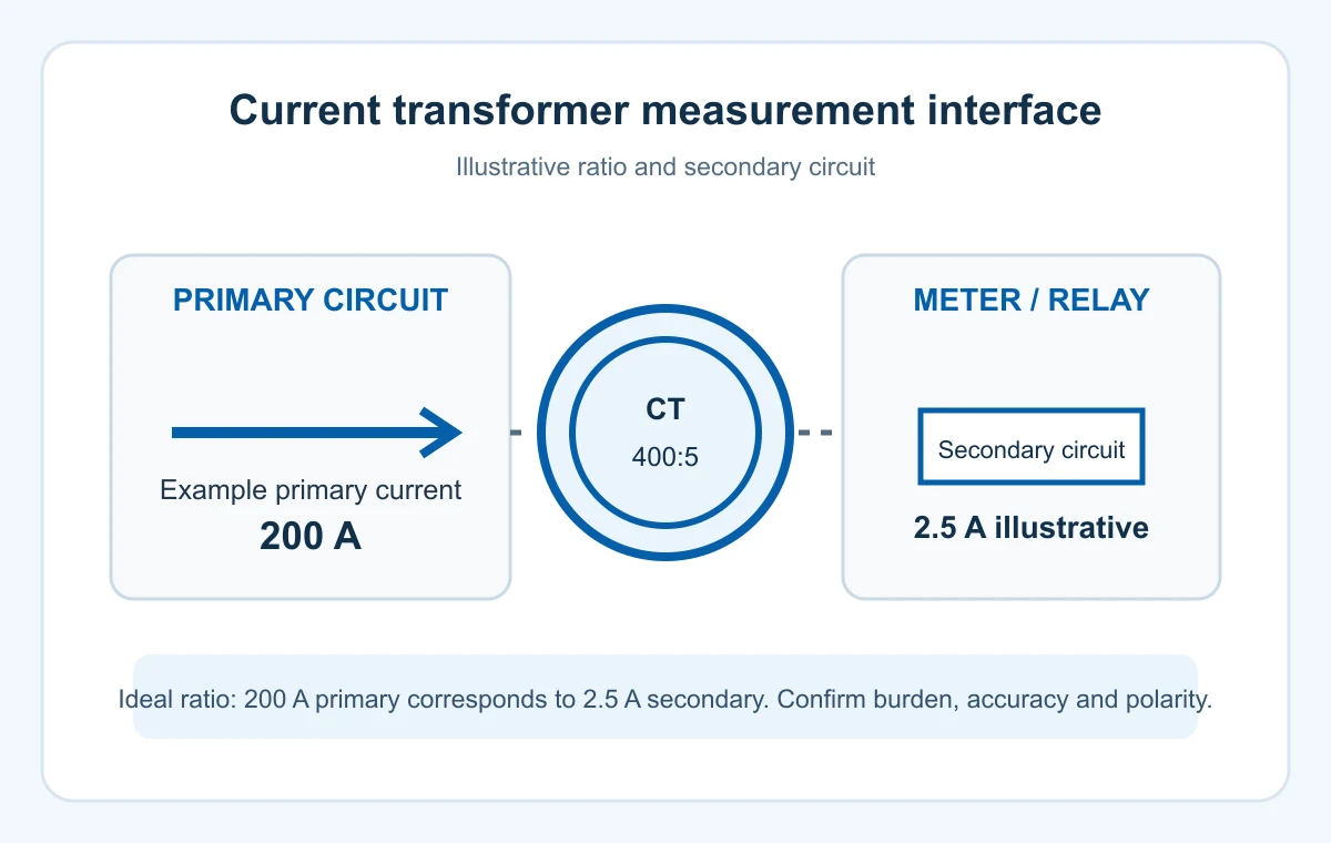
Example — ideal current transformation
400 A : 5 A = 80 : 1
200 A primary → 2.5 A secondary
Set the meter or relay for the installed CT ratio. Confirm the instrument range, terminal polarity and phase identification from approved drawings.
Check burden and accuracy together
The connected instrument and secondary leads contribute to burden. Compare the specified accuracy class, rated burden and expected operating range. Metering and protection duties have different performance requirements, especially near fault conditions and saturation.
| Item or condition | What to compare | Input or result |
|---|---|---|
| Ratio example | 400 A primary : 5 A secondary | 200 A gives 2.5 A ideally |
| Accuracy duty | Metering or protection | Class, burden and operating range |
| Installation | Opening, polarity and terminals | Approved connection drawing |
Prepare installation and test records
Record conductor or busbar dimensions, CT opening, mounting space, insulation requirements and secondary lead routing. Keep the approved connection drawing and test records with the instrument schedule.
CT secondary safety: Qualified personnel must follow the manufacturer's shorting and isolation procedure. An energized CT primary requires a correctly closed or shorted secondary circuit.
Coordinate the CT mounting arrangement with the transformer, switchgear and meter or relay drawings. Use the approved product configuration and system documentation for final clearances and connections.
Frequently Asked Questions
Is a CT interchangeable with a voltage transformer?
A CT monitors current; a voltage transformer provides a scaled voltage signal. Specify each for its own instrument input.
What belongs in a CT enquiry?
Include ratio, accuracy duty, burden, insulation level, frequency, mounting dimensions and the connected meter or relay.
Prepare a complete CT enquiry
Share the ratio, accuracy duty, burden, insulation level, frequency, mounting dimensions and connected meter or relay.