Transformer Technical Guide
Volts vs Amps in Electrical Equipment Ratings
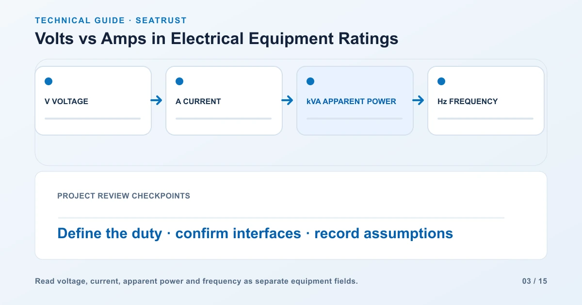
Read voltage, current and capacity together before copying equipment ratings into a project brief.
Volts measure electrical potential difference. Amps measure electric current, the rate at which charge flows. Equipment specifications use both because the supply voltage and the current carried by the equipment answer different questions. Start by reading the units and identifying the side of the equipment to which each rating applies.
Compare voltage and current
Voltage is an electrical potential difference measured in volts, with the unit symbol V. A specification should identify the two points being compared. In a three-phase system, line-to-line and line-to-neutral voltages describe different connections. Keep the voltage notation next to the value when reading a drawing or copying a rating into an equipment schedule.
Electric current is the rate of charge flow and is measured in amperes, shortened to amps, with the unit symbol A. The symbol I is commonly used for current in formulas. A transformer's rated current, a load's operating current and a protective device's current rating refer to different parts of a system. Copy the equipment identifier and operating condition with the value.
Voltage and current are distinct quantities, so a number in volts cannot be converted into amps by changing its unit label. To calculate a relationship, supply information about the load or power. In a simple resistive DC example, 12 V across 6 ohms produces 2 A. Changing the resistance changes the current while the same 12 V supply is maintained.
See why current changes across transformer windings
Consider an illustrative single-phase transformer rated 10 kVA with 240 V and 120 V windings. Dividing 10,000 VA by the winding voltage gives approximately 41.7 A at 240 V and 83.3 A at 120 V. These values describe rated-current relationships on the two sides. They help explain the nameplate fields; the actual operating current depends on the connected load and operating conditions.
| Winding | Rating used | Corresponding rated current |
|---|---|---|
| 240 V side | 10 kVA | 10,000 / 240 = approximately 41.7 A |
| 120 V side | 10 kVA | 10,000 / 120 = approximately 83.3 A |
Read voltage, current and power units
Watts describe real power. Volt-amperes describe apparent power in AC equipment. For a single-phase AC load, apparent power uses RMS voltage multiplied by RMS current. Real power also depends on power factor. Record kW, kVA and power factor separately when comparing loads, then use the dedicated conversion guide for a full single-phase or balanced three-phase calculation.
| Quantity | Unit | Question it answers |
|---|---|---|
| Voltage | V or kV | What potential difference applies between the specified terminals? |
| Current | A | What current flows, or is rated to flow, in the identified circuit? |
| Real power | W or kW | What real power is used or supplied in the stated operating condition? |
| Apparent power | VA or kVA | What apparent-power rating or load applies? |
| Frequency | Hz | What AC frequency is required? |
| Energy | kWh | How much electrical energy is used over time? |
核对铭牌与运行记录
Suppose a 10 kVA, 240/120 V single-phase transformer supplies a load drawing 30 A at 120 V. The measured secondary apparent power is 120 × 30 = 3,600 VA, or 3.6 kVA. The secondary nameplate current remains approximately 83.3 A. The measurement describes one operating condition; the nameplate describes the rated duty.
Record voltage and current at the same time and identify the load state. For a balanced three-phase calculation, use line-to-line voltage with line current in S = √3 × VLL × IL. A load with unbalanced phase currents needs phase-specific measurements and analysis.
| Document | Keep together | Next action |
|---|---|---|
| Nameplate | kVA, winding voltage, phase, frequency | Confirm equipment rating |
| Operating log | Voltage, current, timestamp, load state | Establish actual demand |
| Enquiry schedule | Required load and supply arrangement | Define the proposed transformer |
Use the power triangle load worksheet when the load list includes kW and power factor.
Prepare a complete enquiry
Record the required capacity, primary voltage, secondary voltage, phase arrangement and frequency. Identify whether each three-phase voltage is line-to-line or line-to-neutral. Add the load schedule and the intended installation conditions. If a current figure comes from existing equipment, include the nameplate photograph and identify whether it is a rated value or an operating measurement. This gives the engineering team the context needed to review the specification.
FAQ
Is a 10 A rating the same as a 10 V rating?
The 10 A value describes current; the 10 V value describes voltage. Read each with its equipment and terminal information.
Does higher voltage always mean higher energy use?
Energy use depends on real power and time. Use the load's operating power and hours, together with its actual operating conditions, to assess energy use.
Why do the two transformer windings have different current ratings?
For the same apparent-power rating, a lower winding voltage corresponds to a higher rated current. Identify the correct winding voltage before calculating the value.
Which details should accompany an amperage figure?
Include the equipment identifier, voltage, phase arrangement and whether the current is a nameplate rating or an operating measurement.
Prepare the voltage and load information
Share the primary and secondary voltages, required capacity, phase, frequency and load schedule for a transformer review.