Transformer Engineering Blog
Power Triangle: How to Read kW, kVAR and kVA for Transformer Planning
Turn active, reactive and apparent power into a traceable transformer load schedule.
A power triangle connects real power, reactive power and apparent power. Its practical value is that it helps turn a list of loads into the kVA demand seen by a transformer. Start with each load's kW and power factor, calculate its reactive power, then combine the loads that operate together.
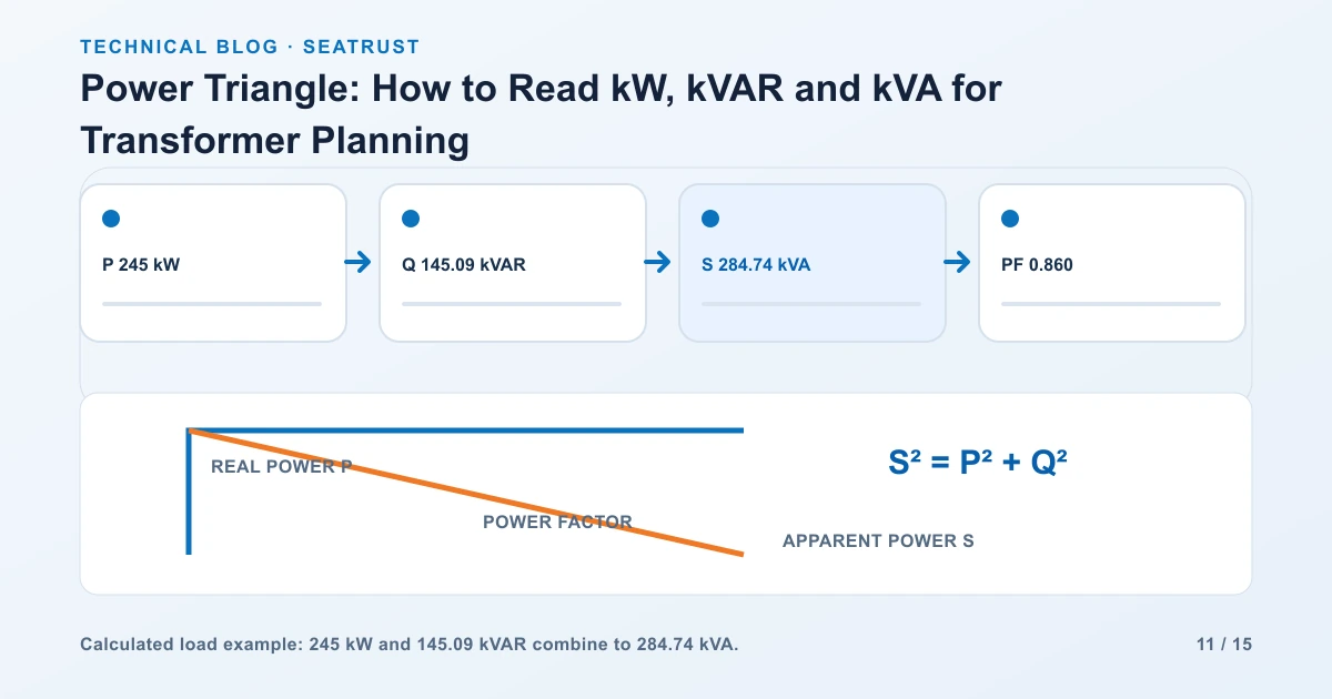
The worked schedule below combines three illustrative loads. Together they draw 245 kW and approximately 145.1 kVAR, giving about 284.7 kVA at a combined power factor of 0.86. The steps show why adding the individual kVA values gives a slightly different result.
Power triangle components and formulas
The horizontal side represents real power P, measured in kW. It includes power converted to useful output and real losses. The vertical side represents reactive power Q, measured in kVAR. The hypotenuse represents apparent power S, measured in kVA. Use positive Q for lagging inductive demand and negative Q for leading capacitive demand in the convention used here.
| Quantity | Formula | What the result tells you |
|---|---|---|
| Apparent power | S = √(P² + Q²) | Combined kVA at the stated operating condition |
| Power factor | PF = P / S | Real power relative to apparent power |
| Apparent power from kW | S = P / PF | kVA when kW and PF are known |
| Reactive power | Q = P × tan(arccos PF) | kVAR magnitude; assign the leading or lagging sign |
| Phase angle | θ = arccos PF | Voltage-current displacement for the sinusoidal model |
These triangle relationships use sinusoidal steady-state quantities. Loads with significant waveform distortion need the measured true power factor and harmonic information as part of the equipment review. OpenStax's AC power chapter explains the underlying relationship between RMS quantities, phase and average power.
Collect a useful load row
For each load, record electrical input kW, power factor and whether it operates during the selected scenario. For a motor, distinguish shaft-output kW from electrical-input kW; include efficiency if the schedule begins with mechanical output.
Retain the source of the number in the engineering worksheet: nameplate, measured demand or design value. A measured 30-minute peak and a motor's rated output describe different operating conditions. Keeping them separate prevents a tidy-looking total from hiding inconsistent inputs.
Also record voltage, phase, starting method and unusual load behavior. Volts and amps explains which fields belong together when the available information starts with current rather than kW.
Combine three loads
Assume the three loads below operate together on a balanced three-phase supply. For this calculation, their voltage and current are sinusoidal and all three power factors are lagging. The kW values are electrical input power.
| Illustrative load | P, kW | PF | S = P/PF, kVA | Q, kVAR |
|---|---|---|---|---|
| Motor group | 120 | 0.80 lagging | 150.00 | 90.00 |
| Lighting and controls | 35 | 0.95 lagging | 36.84 | 11.50 |
| HVAC unit | 90 | 0.90 lagging | 100.00 | 43.59 |
| Combined operating demand | 245 | 0.860 derived | 284.74 derived | 145.09 |
Calculate each row's kVA using S = P/PF.
Calculate each row's kVAR using Q = √(S² − P²), with the correct sign.
Add real power: Ptotal = 120 + 35 + 90 = 245 kW.
Add reactive power: Qtotal = 90 + 11.50 + 43.59 = 145.09 kVAR.
Calculate Stotal = √(245² + 145.09²) = approximately 284.74 kVA.
Calculate PFtotal = 245/284.74 = approximately 0.860.
Adding the individual apparent-power magnitudes gives 286.84 kVA. The vector result is lower because the loads have different power-factor angles. Add P and Q first when those quantities are available; keep unrounded values in the calculation.
Compare operating scenarios
A transformer may see several operating patterns. Use a separate column or worksheet for normal production, seasonal peak and a planned outage. This makes load transfer and shutdown assumptions visible.
| Scenario | Loads included | P, kW | Q, kVAR | Combined S, kVA |
|---|---|---|---|---|
| Normal production | All three illustrative groups | 245 | 145.09 | 284.74 |
| HVAC stopped | Motors, lighting and controls | 155 | 101.50 | 185.28 |
| Controlled shutdown | Lighting and controls only | 35 | 11.50 | 36.84 |
For the first scenario at 480 V line-to-line, calculated line current is 284,740/(√3 × 480), approximately 343 A. Starting current and short-duration transients belong in separate study inputs; the table represents steady operating demand.
Turn the result into a transformer selection input
The load calculation establishes demand. The next step is to compare that demand with available transformer ratings under the required ambient, cooling and loading conditions.
| Review item | Information to add |
|---|---|
| Future growth | Named future loads, kW/PF and expected operating combination |
| Motor starting | Starting method, starting duty and permitted voltage dip |
| Harmonics | Nonlinear load inventory and measured or specified distortion |
| Environment | Ambient temperature, altitude, enclosure and room cooling |
| System duty | Supply voltage, winding connection, impedance and fault-study requirements |
| Continuity | Loads transferred during a source or transformer outage |
Use the transformer sizing guide to assemble these fields. Keep expansion allowance explicit in the project brief instead of hiding it inside a rounded load total.
FAQ
Why is combined kVA different from the sum of individual kVA?
Apparent power is a vector magnitude. Loads with different power-factor angles have different proportions of P and Q. Add their real and reactive components before finding the combined magnitude.
Can I average three power-factor values?
Calculate total kW and kVAR, then derive the total power factor. An unweighted average gives a small load the same influence as a large one.
What changes if a load is leading?
Assign negative Q to that load under this convention, then add the signed values. Review any compensation equipment with the system's harmonic and operating conditions.
Which information makes a capacity enquiry useful?
Provide a load schedule, supply voltages, frequency, phase arrangement, operating scenarios, growth plan and installation conditions.
Prepare the load schedule for review
Send the load rows and their operating combinations with the required primary and secondary voltages. Include the room or site conditions so capacity and installation requirements can be reviewed together.