Transformer Fundamentals
Isolation Transformers and Winding Separation
Learn how isolation, voltage ratio and grounding requirements shape an equipment specification.
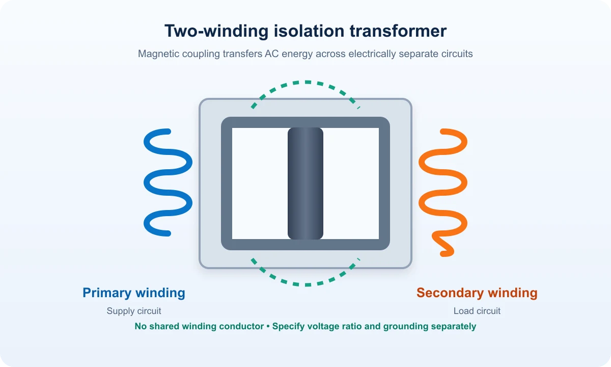
An isolation transformer uses electrically separate primary and secondary windings. Electrical separation defines isolation; the voltage ratio and grounding arrangement are separate specification decisions.
Separate isolation from voltage change
Electrical separation and voltage conversion describe different functions. A two-winding transformer can provide isolation with equal or different nominal voltages. Compare the winding diagram before using a product label to infer its connection.
Coordinate the secondary system
Grounding, protective devices and any required neutral arrangement belong to the system design. Document how the secondary supply will serve the load, including its fault path and protective coordination.
Two-winding construction
Compare: Separate primary and secondary
Result: Electrical separation
Autotransformer
Compare: Shared winding section
Result: Common electrical connection
Application review
Compare: Voltage and grounding
Result: System specification
Compare the construction
An autotransformer uses a shared winding section, while a two-winding isolation arrangement separates the circuits electrically. Use the distinction to prepare a technical enquiry with the required supply, output and application.
Frequently Asked Questions
Does isolation require a 1:1 voltage ratio?
Isolation describes winding separation. The specified voltage ratio may be equal or different.
Does isolation replace protective design?
The installation still requires coordinated grounding, protection and safe operating procedures.
Discuss the required configuration
Share the required supply and output voltages, grounding and neutral needs, load details and application with the project team.