Transformer Technical Guide
Electrical Room Planning for a Transformer
Coordinate the transformer footprint, heat rejection, access and cable routes before procurement.
An electrical room needs coordinated equipment, thermal, structural and access planning. Start with the proposed transformer and connected switchgear, then review the room as a complete installation. Confirm the required layout with the project's electrical, mechanical and civil designers.
Build the equipment schedule first
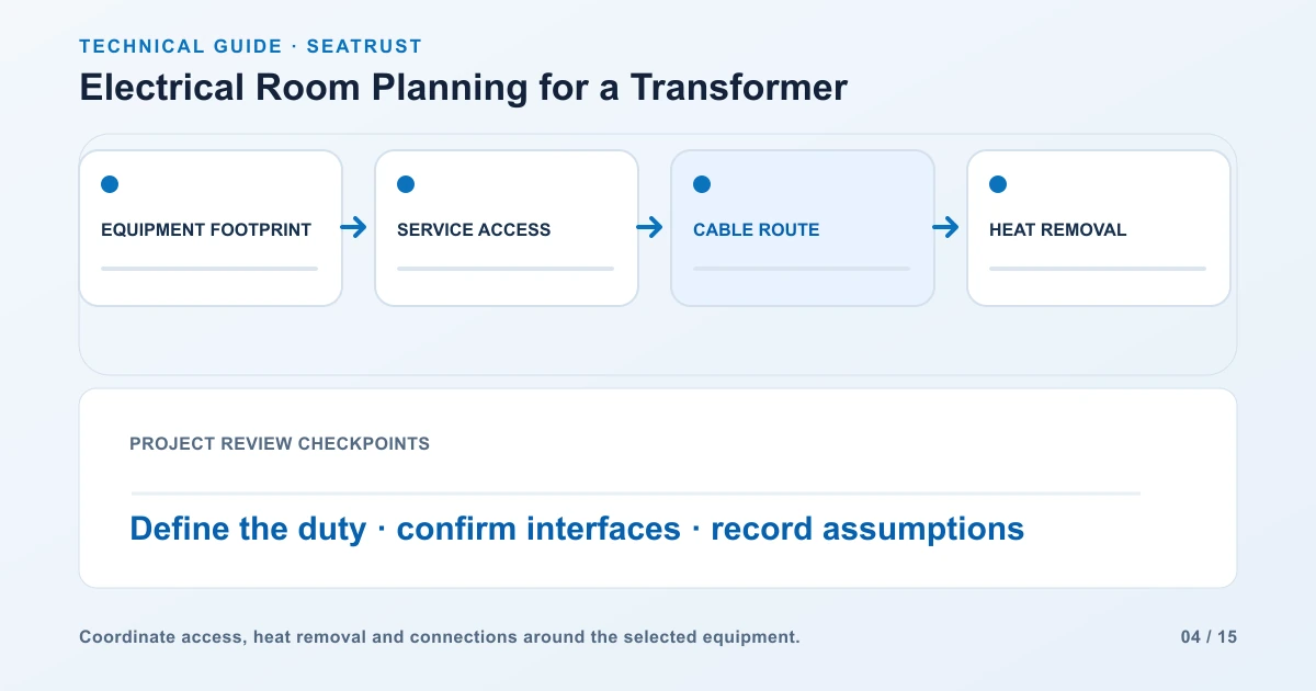
List the transformer, switchgear, panels and other equipment planned for the room. Record each item's dimensions, weight, voltage, heat-loss information and access requirements. For the transformer, obtain the selected enclosure and connection arrangement. Use these documents as inputs to the room layout so the design accommodates the actual equipment.
Plan working space, delivery and replacement access
Draw the installed equipment footprint, the space required to operate and service it, and the access route through the room. Show door swings and removable covers. Have the responsible designer determine the applicable working-space and access requirements for the equipment voltage and local rules. Keep stored materials out of the designated working and escape routes.
Trace the route from unloading to the final position. Record door openings, turning points, corridor width, floor loading information and lifting access. Check the largest handling configuration against the supplier's transport dimensions. A replacement route matters as much as the first installation: identify any removable panels or doors that are part of the plan.
Calculate the room heat load and cooling inputs
Give the mechanical designer the transformer's loss data at the intended operating conditions and the other equipment heat loads. Identify the manufacturer's air inlet and outlet locations. Review ventilation or cooling together with room temperature, air quality and maintenance access. Keep the airflow path clear after cable trays, pipes and adjacent equipment are added to the layout.
For an illustrative room heat load of 5 kW and an allowed air temperature rise of 10 K, a simple sensible-heat calculation uses airflow = heat / (air density × specific heat × temperature rise). With air density 1.2 kg/m³ and specific heat 1,005 J/(kg·K), the result is 5,000 / (1.2 × 1,005 × 10) = 0.415 m³/s, approximately 1,490 m³/h.
The ventilation designer then includes altitude, intake conditions, pressure loss through louvers and filters, equipment placement, and the building's fire and environmental requirements. Put the approved airflow and intake/exhaust locations on the room drawing.
Review cable and terminal interfaces
Mark where the high- and low-voltage connections enter the transformer enclosure and where the adjacent equipment is located. Provide the intended cable or bus connection arrangement to the supplier. Coordinate routing, support and the space needed at terminations. Keep the connection details aligned with the current general-arrangement drawing as the design develops.
现场条件分流
| Room condition | Design question | Information for the transformer enquiry |
|---|---|---|
| Dusty intake air | How will filters and heat removal be coordinated? | Dust exposure, cleaning access, ambient temperature |
| Restricted door or corridor | How will the unit enter and later leave the room? | Clear route dimensions, turns and handling plan |
| High ambient temperature | What loading and cooling duty must the unit meet? | Ambient range, load profile and ventilation proposal |
| Shared services | How are water, drainage and other services separated? | Coordinated building layout and exposure assessment |
Compare dry-type transformer families once the electrical duty and room conditions are defined.
Issue a coordinated room package
Release the room plan with an equipment schedule, transformer outline drawing, connection details, mechanical design inputs and delivery plan. Record the approved drawing revision used for each part of the work. At installation, compare the equipment positions and access routes with that package and close discrepancies before the room is handed over.
| Drawing or record | Required detail | Review owner |
|---|---|---|
| Equipment arrangement | Footprint, service panels, door swings and access zones | Electrical designer and equipment supplier |
| Delivery route | Packaged dimensions, transport weight, openings and turning points | Site logistics and structural team |
| Heat removal | Equipment loss data at stated duty, allowable ambient conditions and air paths | Mechanical designer and equipment supplier |
| Cable and bus interfaces | Terminal positions, entry direction and connection space | Electrical designer and installer |
| Coordinated floor plan | Maintenance access, egress, adjacent services and future equipment | Architect and responsible project engineers |
| Approved release record | Drawing revisions, responsible reviewers and closed interface actions | Project coordinator |
FAQ
Can room size be chosen from kVA alone?
Use the actual equipment dimensions, installation requirements, access needs and room systems.
What helps the ventilation designer?
Provide the relevant equipment losses, loading conditions, installation requirements and other room heat sources.
Request equipment data for the layout
Share the room plan and transformer duty to coordinate dimensions, connection points and operating information.