Grounding and Protection
Neutral Grounding Resistors for Transformer Systems
Its purpose is to limit ground-fault current to the level established by the system design while supporting fault detection and the required protective response.
A neutral grounding resistor connects a system neutral to ground through a selected resistance. Its purpose is to limit ground-fault current to the level established by the system design while supporting fault detection and the required protective response.
Establish the grounding arrangement
Identify the transformer winding connection and whether its neutral is available. The electrical study establishes the grounding method, target fault current and clearing strategy. Include system charging current and required continuity of service when reviewing high-resistance or low-resistance grounding.
Read resistance with voltage and duration
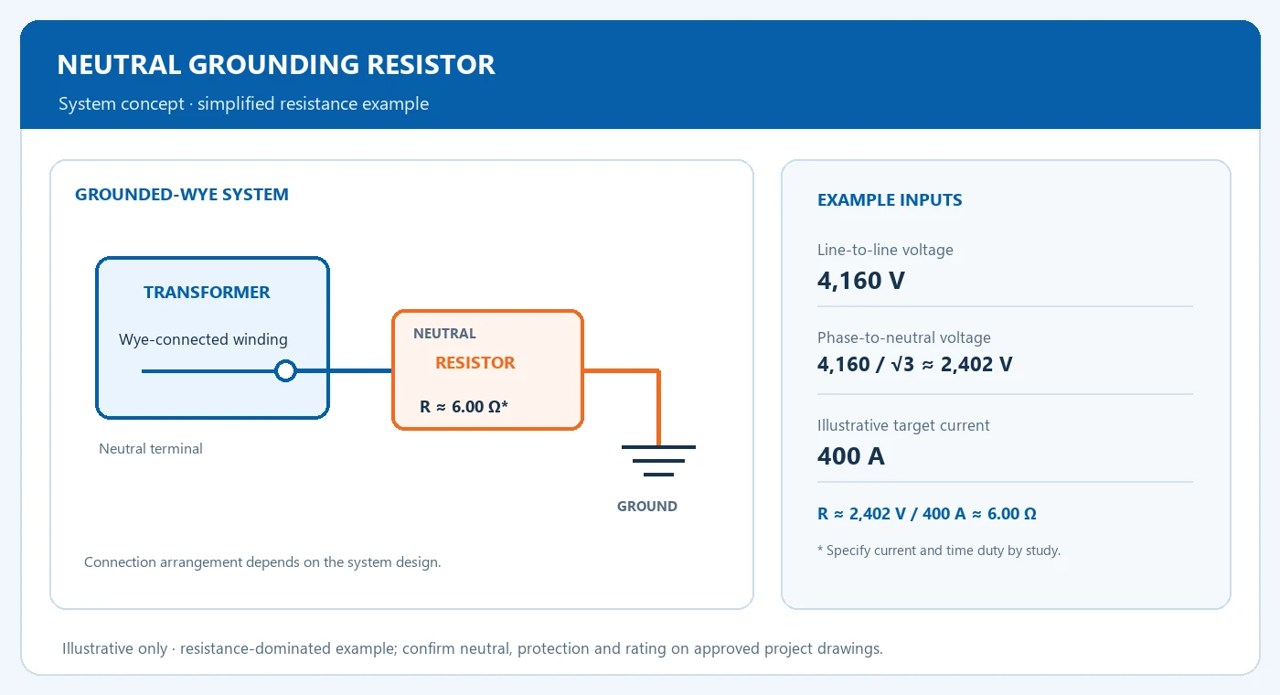
For a simplified, resistance-dominated example, a 4,160 V line-to-line wye system has about 2,402 V from phase to neutral. A 400 A target corresponds to approximately 6.00 ohms. The resistor also needs a specified current and time rating; this calculation supplies only an illustrative resistance.
Example · resistance-dominated calculation
VLN = 4,160 V / √3 ≈ 2,402 V
R ≈ VLN / I = 2,402 V / 400 A ≈ 6.00 Ω
This simplified value does not set the resistor’s current-time duty or replace the system grounding and protection study.
| Item or condition | What to compare | Input or result |
|---|---|---|
| System input | 4,160 V line-to-line wye | 2,402 V phase-to-neutral example |
| Resistance example | 2,402 V / 400 A | Approximately 6.00 ohms |
| Assembly specification | Current, time duty and monitoring | Protection study and terminal drawing |
Coordinate the assembly and protection
Specify neutral insulation, enclosure, ambient conditions, connection location and resistor monitoring. Put the current sensor and protective relay on the system drawing. Confirm the transformer neutral terminal, grounding connection and responsibility for each supplied component before releasing the equipment schedule.
Neutral and connection
Confirm the available neutral terminal and grounding connection on the transformer drawing.
Current and time duty
Use the protection study to establish the specified fault current and duration.
Monitoring and protection
Coordinate the current sensor, protective relay and monitoring requirements on project drawings.
Frequently Asked Questions
Which voltage is used in the simple resistance calculation?
Use the voltage across the resistor during the specified fault condition. In the illustrated grounded-wye case, that is phase-to-neutral voltage.
What determines the final current rating?
The grounding and protection study establishes the target current and duration for the actual network and operating requirements.
Coordinate neutral grounding requirements
Share the system voltage, winding and neutral details, fault-current target, time duty, monitoring and protection inputs for review.